- Connect Ethernet cable to HMI and PC.
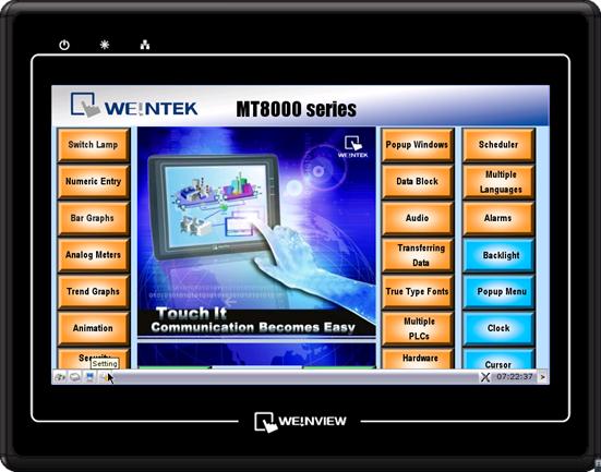
- Go to HMI’s system setting bar which is at the bottom of the screen, and select
 to see the IP address in the HMI. If there is no IP address, please click
  .
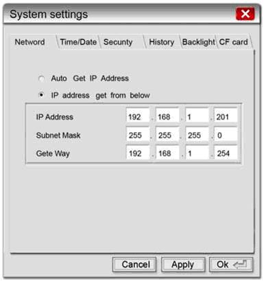
. - After clicking , system settings window appears, there are two items in Network tab, if you select “Auto Get IP address”, HMI will automatically detect IP address, or you can select “IP address get from below” to assign IP address for HMI.
- Note: after selecting “Auto Get IP address” => press Apply => press ok => go to for seeing HMI IP.
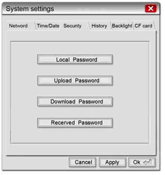
- 4. Select Security tab to set the Download password, the default is 111111, or you can reset the Download password.
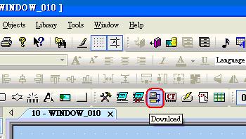
- 5. After setting the download password, go to EasyBuilder Pro and select Download icon.
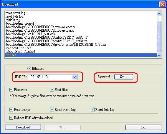
- 6. Fill in the HMI IP address and download password, and then press Download button.
HARDWARE SUPPORT / FAQ
We are continually adding support below. Please contact us if you are unable to find the answer(s) to your question(s).
The MT-600X / MT8000X Series takes one coin type of CR2032 lithium battery to keep the RTC running. Battery specification: CR2032 3V lithium battery.
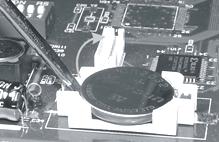
- Turn off the screen and open its rear cover.
- Use a screwdriver to take off the battery from the socket.
- Insert a new battery into the socket.
- Put on the rear cover.
- Connect a USB Keyboard on HMI
- After reboot HMI, enter [Delete] for go to setup window.
- Go to setup window and select [CMOS Feature] for setting the date and time.
- Go to [Load optimized default] => click yes =>click Enter => Click F10 for saving the settings.
Note: Correct way to insert the new battery
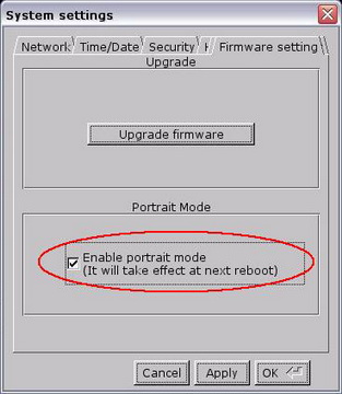
i series touch panel screen supports portrait display. The following steps introduce how to apply this function.
Notice: this function is provided by i series only.
- This picture shows an example of landscape display on MT8100i.
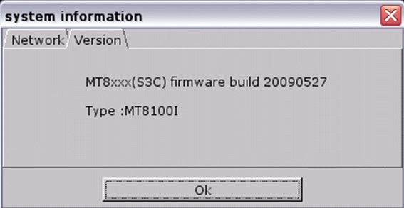
- Firmware version: 20090527 or later:
- Software version: V3.20 2009.07.30 or later:
- First, setup the HMI by selecting “Enable portrait mode” under System Settings-Firmware setting tag. Then restart the HMI.
- Run the EasyBuilder Pro program and click File/New to create a new project file. Choose i series model name from the “Model” pull-down list and set the “Display Mode” to “Portrait”. Click “OK” button.
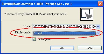
- A new project file is created as follows:
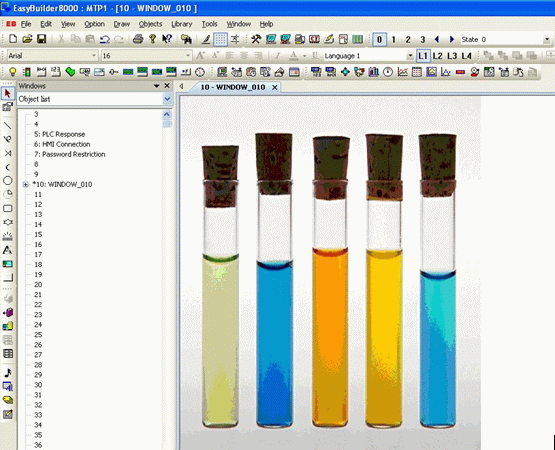
- Download project to the touch panel HMI. The HMI now displays in portrait orientation.
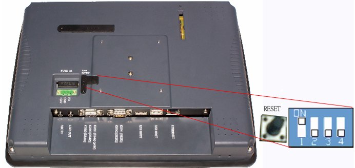
- Switch SW1 to ON position (as shown in picture 1). Press “Reset” or re-plug in the HMI.
Picture 1:
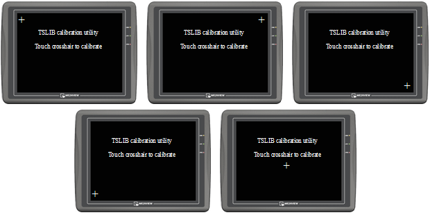
- Touch panel calibration screen is shown as follows. Put the HMI screen perpendicularly to your line-of-sight, and point your finger at the center of the cross icon displayed on the screen. The cross icon will appear in five positions of the screen: upper-left corner, upper-right corner, lower-right corner, lower-left corner and the center, as shown in (picture 2).
Picture 2:
- The HMI will automatically restart after finishing calibration. Afterwards, a warning message will appear (as shown in picture 3).
Picture 3:
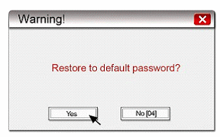
- The warning message shows “Restore to default password?”. Users can select “Yes” to restore password or select “No” to discard. If there is no response from the user within 10 seconds, the warning message will automatically be closed.
Notice: If no further operation other than calibration process to make, click “No”.
- Click “Yes” button. A popup window would show up (as shown in picture 4).
Picture 4:
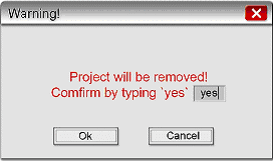
- The popup window will check out again if the user really wants to restore the password and will ask the user to enter “yes” and click “OK” button to confirm it. If the user doesn’t want to restore password, click “Cancel”.
- The password of factory default setting is 111111 for MT8000/6000 series. After initialization process, the project files and data stored in the touch panel HMI will be completely erased.
- The upload and download password need to be reset in order to transfer project files correctly after initialization (as shown in picture 5).
Picture 5:
i series touch panel supports user to define their own startup screen, such as enterprise trademark logo, etc. The following steps introduce how to apply this function:
Notice: this function is provided by i series only.
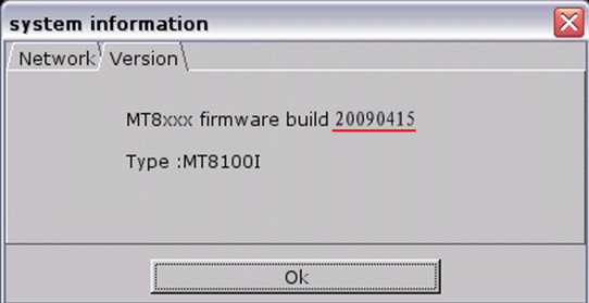
- Firmware version: 20090415 or later:
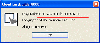
- Software version: V3.20 2009.07.30 or later:
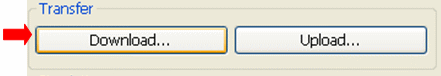
- Run the Project Manager program, click “Download” button:
- When the “Download” window shows up, select “Startup screen”, and click “Browse…” button. Choose an image which will be used as startup screen in HMI.
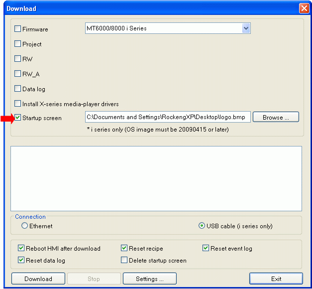
- Click “Download” button. After downloading, restart touch panel HMI. The startup screen is already changed to the image downloaded by user.
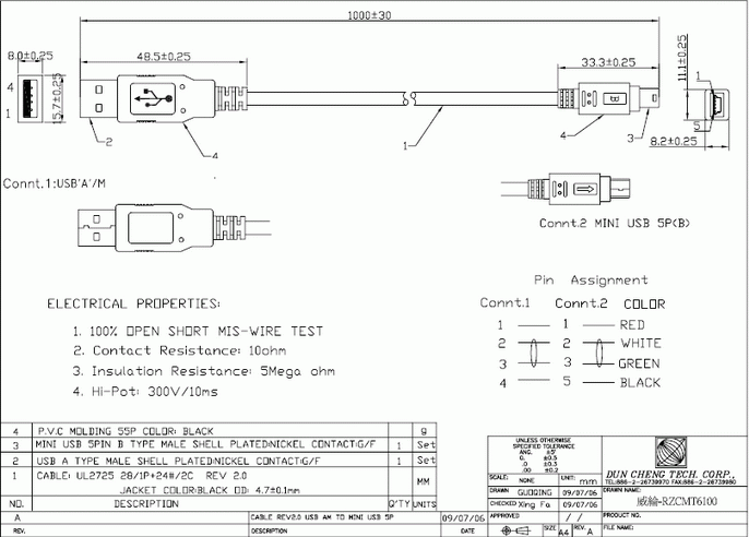
USB cable specification: HI-SPEED USB Revision 2.0 SHIELDED 24AWG
Notice:
- The USB port of PC must support USB2.0 standard.
- The USB cable should be shielded with 2 layers: Aluminium foil shield + net shield.

- The length of USB cable shouldn’t be too long. 1 meter of length is good.
- If a desktop is used, the USB cable should be plugged into the back panel instead of the front, since that the extension line connected between main board and the front panel USB port is usually not shielded.
- When downloading project through USB cable, please do not connect PLC with HMI COM port or using RZCMT6100 MT6000/8000 i series download cable to download project to HMI for protect HMI from unexpected damage.
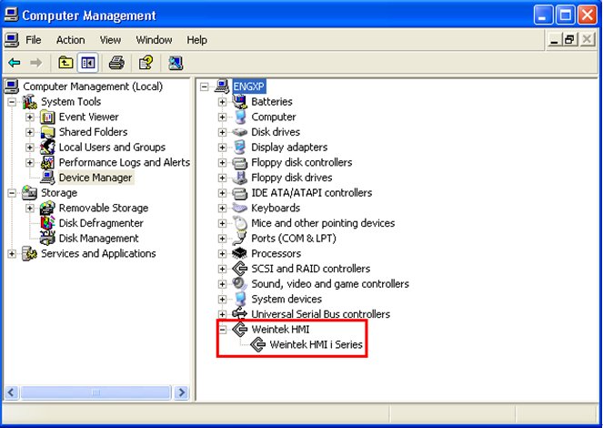
- If downloading cannot be performed, it might be caused by the incompatible USB driver on PC. You can try it on another PC or go to Computer Management/Device manager for checking if USB driver is installed correctly as illustration below.
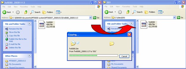
MT8000/6000 OS Image version is 20081013 or later, which support using USB disk or SD card to update OS image. The update process is similar to downloading project to the touch panel HMI. The following example shows how to update OS image by using USB disk.
- Find the corresponding OS image document to the MT8000/6000 and copy it to the USB disk (as shown in picture 1). For example, copy it to the 001 folder that is previously created.
Picture 1:
- Insert the USB disk into the USB port of the MT8000/6000.
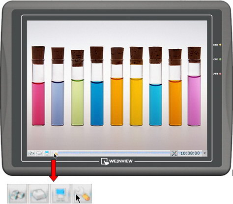
- Move the cursor to the lower-right corner of the touch panel screen. A “<” button (as shown in picture 2) will show up, click it to open system setting bar (as shown in picture 3).
Picture 2:
 Picture 3:
- Click “setup” button, a popup window will appear and ask users to input the password (as shown in picture 4).
Picture 4:
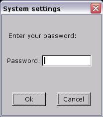
- Enter the correct password (factory default setting password: 111111), and then the “System settings” window will show up. Switch to the “Upgrade firmware” tab (as shown in picture 5).
Picture 5:
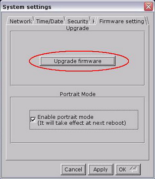
- Click “Upgrade firmware” button, a “Pick a Directory” popup window will show up (as shown in picture 6).
Picture 6:
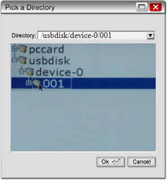
- Open the usbdisk folder, select the 001 folder, then click “OK” button.
- Start upgrading the OS image. This process will take a few minutes. The progressing bar indicates the upgrading status (as shown in picture 7).
Picture 7:
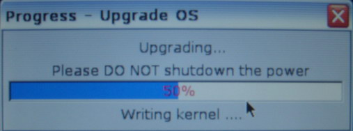
- After the upgrading process is completed, the system will automatically restart; a touch panel calibration is recommended.
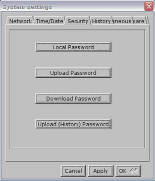
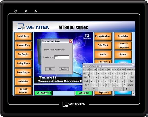
MT6000/8000 series HMI provide reliable password protection. The factory initially set password to 111111. Users can setup their own password, as follows:
- Click the “<” icon on the lower-right corner of the screen, and the system setting bar will appear. Click “Setting” icon, a popup window shows up and asks users to enter the password as shown below:
- Enter password. The default is “111111”. Click “OK” and the “System Settings” window shows up.
- Switch to “Security” tab, there are four kinds of password can be changed as shown in the following picture:
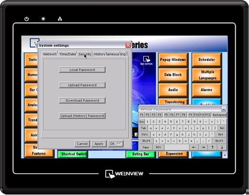 Local Password
Password that is needed while entering “System Settings”;Upload Password
Password that is needed while uploading program;Password that is needed while downloading program;Upload (History) Password
Password that is needed while uploading data and event log file; - Click “Upload Password” will show the dialog below. Enter the new password twice. Comparing two passwords, if they are the same, a “Password match” message will show up. Otherwise, a “Password NOT match !” message will show up. Click “OK” to complete.
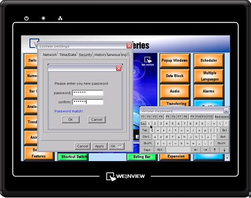 Click “Apply” to activate the new password. Next time the user wants to upload project, he needs to enter the new password.The four kinds of password follow the same process above to be modified.Make sure to enter the correct password to operate the MT6000/MT8000 HMI. The EasyBuilder Pro should setup the same password as the HMI for uploading/downloading program.
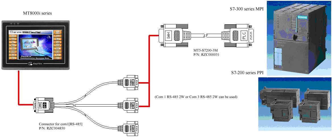
- Built-in MPI with 187.5K baud rate function is available on the MT8150XV2, MT8121XV2, MT8104XH2, MT8100iV2, MT8070iH2, MT8050iV2, MT6100iV2, MT6070iH2, and MT6050iv2.
- Select SIEMENS S7/300 MPI driver for S7-300 and S7-200 PLC, or select SIEMENS S7/200 driver and set the baud rate to 187.5K. (EasyBuilder Pro must be V3.10 or newer for i series and V4.10 or newer for X series.)
- One HMI is able to connect to one 187.5K device only.
- It doesn’t support to use Extended Address mode.
Note: MT8000/6000 series only COM1 available for using 187.5K, COM3 is invalid.
Please refer to below for connection diagram:
-
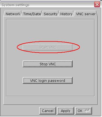
- Enable VNC server and set login password on HMI System Settings / VNC server tab.
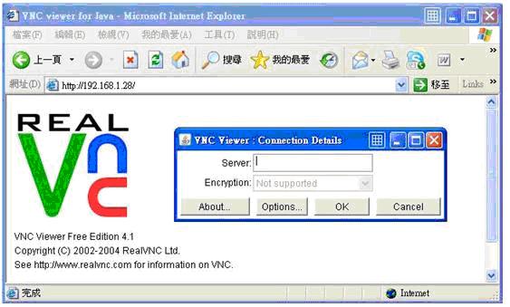
- Install Java for Internet Explorer or install VNC viewer.Java web site: http://java.com
VNC viewer: ftp://ftp.weintek.com/MT8000/utility/vnc-4_1_2-x86_win32_viewer.zip
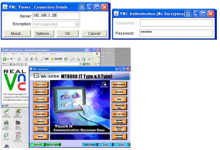
VNC viewer for Pocket PC: ftp://ftp.weintek.com/MT8000/utility/zoomVNC.CAB or http://zoomvnc.com/ - Execute IE, and enter IP address of HMI: http://192.168.1.28 (example)
 Or execute VNC viewer, and enter HMI IP address and password.
Note:
(1) Only available for one user to login to VNC at the same time.
(2) HMI will reject VNC connection if no operation done for one hour. - Enable VNC server and set login password on HMI System Settings / VNC server tab.
- EasyBuilder Pro supports the function of using system tag [LB-9020] to enable/disable system setting bar, or set the [DIP Switch 2] to ON/OFF for activating this function.If using [LB-9020] to control the system setting bar, when LB-9020 set ON, the bar is displayed, and set OFF to hide the system setting bar.When [DIP Switch 2] set ON, the system setting bar is disabled, and when [DIP Switch 2] set OFF, the system setting bar can be controlled. Users have to restart HMI to enable/disable this function.
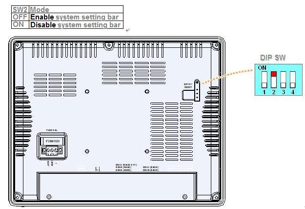 Note:[LB-9020] is available for MT6000/8000 T, X, i series.
[DIP Switch 2] is available for MT6000/8000 i, XV2 series.
- Setting MT8000 VNC function. Please refer to the document from link below.
FAQ_28_How_to_use_VNC_server.pdf - OpenApp Store, search “VNC”. Find “Mocha VNC Lite” and install.
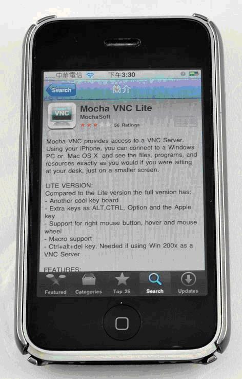
- In Mocha VNC Lite, set HMI IP address, Password, TCP port = 5900. Click “Connect” and users are able to control HMI by iPhone.
.jpg)
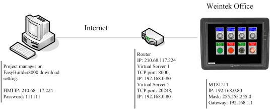
MT8000 port list is shown below.
l Remote HMI TCP port = 8000
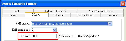
l Download Project through a router
MT8000 Project download TCP port = 20248
When downloading a project through Internet, please make sure that the router supports virtual server or port forwarding first.
l VNC Viewer TCP port = 5900
l http VNC, Java
TCP port = 80
TCP port = 5800
l Ethernet Pass-Thru TCP port = 2000
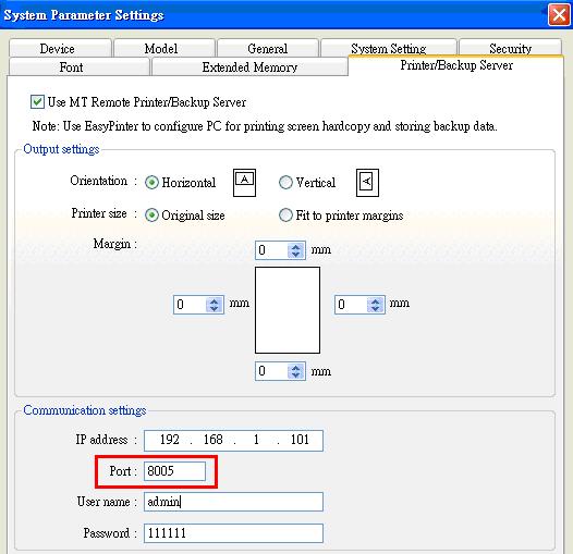
l Printer Server TCP port = 8005
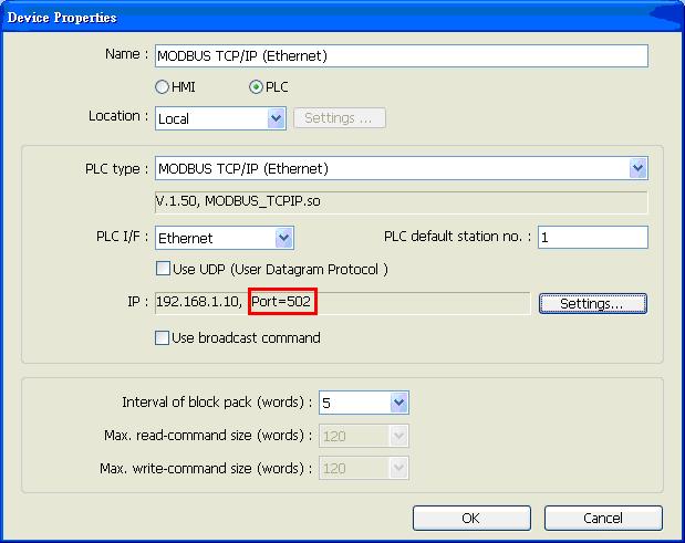
l Modbus TCP/IP port = 502
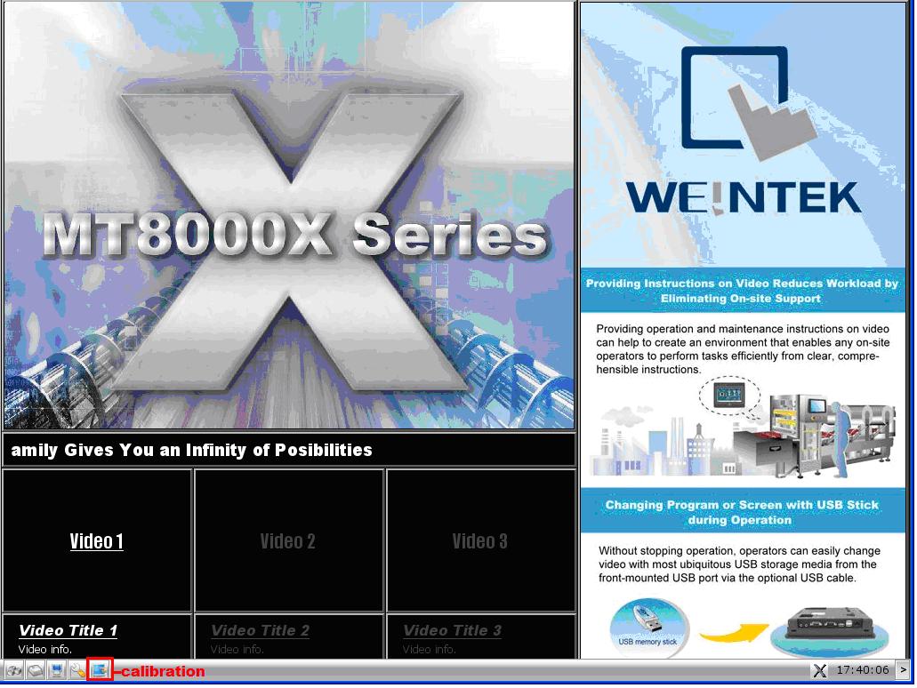
MMT8000 X series HMIs are able to active calibration on the touch screen.
Step 1. Connect a USB mouse with MT8000 X HMI.
Step 2. Go to system setting bar.
Step 3. Click  calibration button to start calibration.
MT6000/8000 HMI operating temperature ranges from 0° to 45°C (32°~113°F). If the unit is under 0°C or overheated, the plastic can expand in heat and shrink in cold. When the HMI suddenly encounters a huge temperature change, the HMI plastic housing (front bezel and rear cover) may be deformed. And when the front bezel is deformed, it will make the touch panel malfunction, since the touch panel is fixed in the front bezel and can be deformed too.
So we strongly recommend customers who need to run their systems in the environment under 0°C to equip a heater in their control box.
On the contrary, when the system is in the environment over 45°C, users shall equip an air conditioner or fan to make heat dissipation well.
[RS232]
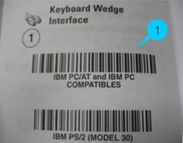
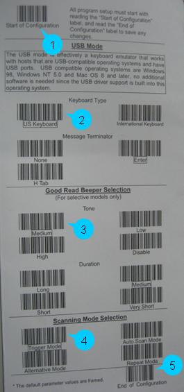
Take symbol type LS1203 as an example, Barcode Scanner should be set before using, and scan from Step1 to Step6 in sequence.
Step 1. [ Keyboard Wedge Interface]
IBM PC/AT and IBM PC COMPATIBLES
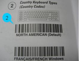
Step2. [ Country Keyboard Types (Country Codes)]
NORTH AMERICAN (Default)
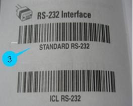
Step3. [RS-232 Interface]
STANDARD RS-232
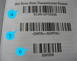
Step4 ~ 6. [Set Scan Data Transmission Format]
SCAN OPTIONS
ENTER
[USB]
Take ZEBEX USB Barcode Scanner as an example, settings should be done before using. Set the Interface first, scan from Step1~Step3.
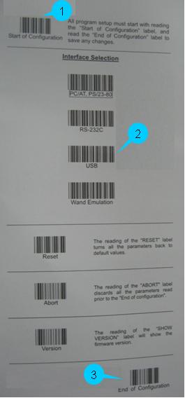
Step1. Start of Configuration
Step2. [Interface Selection] ->USB
Step3. End of Configuration
Now go on to USB Mode basic settings, scan from Step 1~ Step 5.
Step1. Start of Configuration
Step2. [Keyboard Type] -> US Keyboard
Step3. [Good Read Beeper Selection] -> Medium
Step4. [Scanning Mode Selection] -> Trigger Mode
Step5. End of Configuration
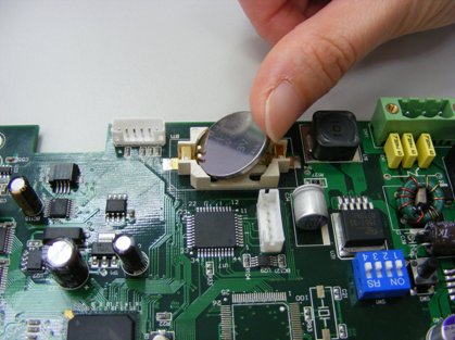
The MT-8000 Series takes one coin type of CR2032 lithium battery to backup the recipe data and keep the RTC running. Battery specification: CR2032 3V lithium battery.
Steps for battery replacement:
- Use ProjectManager to backup the recipe data.
- Turn off the screen and open its rear cover.
- Use a screwdriver to take off the battery from the socket.
- Insert a new battery into the socket.
- Put on the rear cover.
- Reset the RTC time and download the recipe data.
Note: Correct way to insert the new battery
Reading Battery Voltage
EasyBuilder Pro provides LW9008 (32bit-float): battery voltage for detecting i series battery voltage.
If the value of LW9008 battery voltage is lower than 2.8volt, please replace the battery.
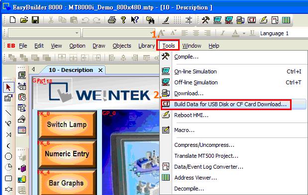
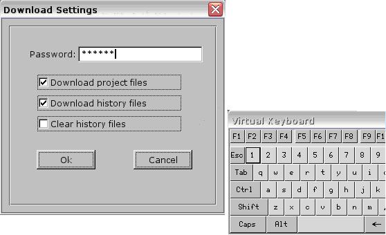
[Download]
Step1. Plug a USB Disk to PC USB port.
Step2. In the EB8000, go to [Tools] / [Build Data for USB Disk or CF card Download…]
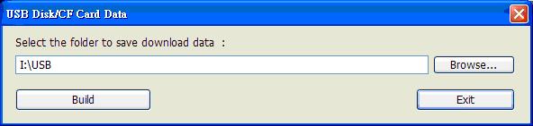
Step 3. Assign a folder name or click [Browse] for saving the project and click [Build]
Step 4. When project is saved in USB, the message will appear as below.

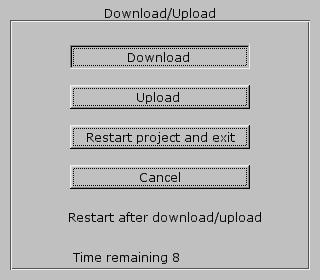
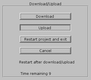
Step 5. Insert USB to HMI USB port, a dialogue box of Download/Upload appears, click [Download].
Step 6. Enter Download password and click [OK]
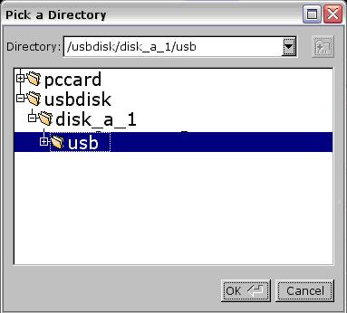
Step 7. Select usb disk -> click usb folder -> click OK to start downloading project.
Step 8. Downloading project Files…

Step 9. After project is downloaded successfully, project will display on the HMI screen.
[Upload]
Step 1. Insert a USB Disk to HMI USB port, a dialogue box of Download/Upload appears, click [Upload].
Step 2. Enter Upload password and click [OK]
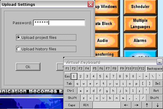
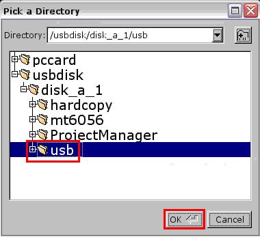
Step 3. Select usb disk -> click usb folder for saving the file to this folder -> click OK to upload project.
Step 4. Uploading Project Files…

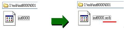
Step 5. Insert USB Disk to PC, Go to 001 and add a suffix “xob” in mt8000.
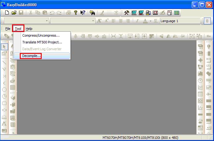
Step 6. Go to EasyBuilder Pro/Tools/Decompiles…
Step 7. Select mt8000.xob in USB disk and click [Decompile]
Step 8. When decompile successfully, click exit and open mtp file in USB disk.
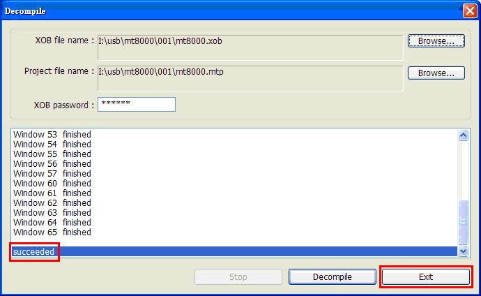
Step 9. Finish uploading procedure.