[Set RW0~RW4 to 16-bit unsigned, RW5~RW13 to 32-bit unsigned]
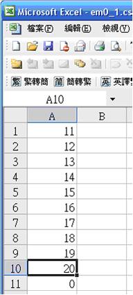
Step 1. Set the data format in Recipe Editor
Order by Phone
1- 425-328-8445
[Set RW0~RW4 to 16-bit unsigned, RW5~RW13 to 32-bit unsigned]
Step 1. Set the data format in Recipe Editor

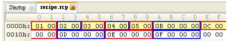
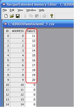
Step 2. The data are shown below. Data 0~Data 4 are the contents of addresses RW0~RW4. Data5~Data9 are the contents of addresses RW5~RW13.
Step 3. The formats seen in HEX edit are listed; low bytes first, high bytes follow.
RW0 = 01 00
RW1 = 02 00
RW2 = 03 00
RW3 = 04 00
RW4 = 05 00
RW5 = 0B 00 00 00
RW7 = 0C 00 00 00
RW9 = 0D 00 00 00
RW11 = 0E 00 00 00
RW13 = 0F 00 00 00
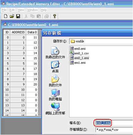
[Transmitting Recipe File]
Step 1. Input ftp address and password, in this example HMI IP is 192.168.1.103, password 111111. EX: ftp://uploadhis:111111@192.168.1.103
Step 2. Click Enter, HMI history records will be shown, the recipe folder is included.
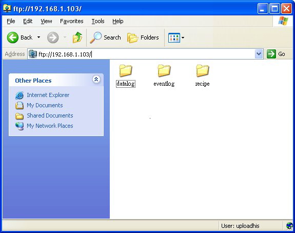
Step 3. Copy the newly built recipe.rcp into recipe folder to finish updating.
The following is an example to illustrate the steps of security feature:
Step 1
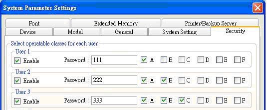
First of all, create a new project. Go to System parameter settings / Security, add three users and set different passwords and classes.
Step 2
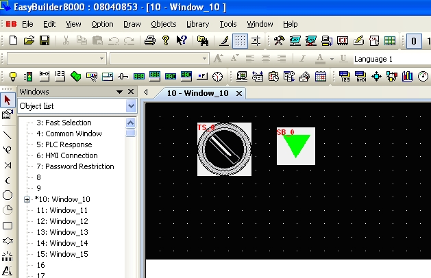
Set objects in Window_10 as below:
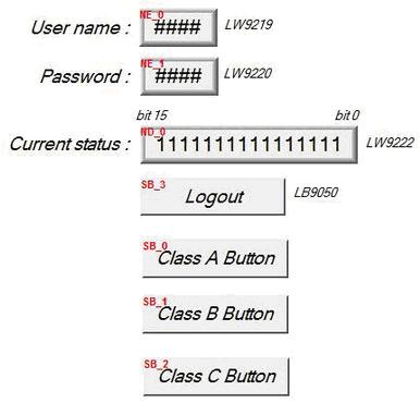
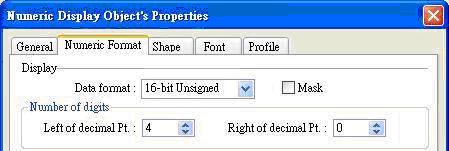
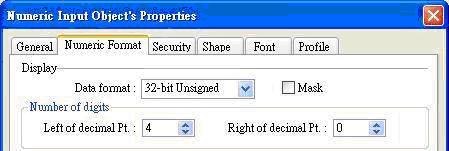
[NE_0] and [NE_1] are Numeric input objects where address are [LW-9219] and [LW-9220] for inputting user ID and password. [LW-9219] is for inputting user ID (1~12), with the length of 1 word, in the form of 16-bit Unsigned as below.
[LW-9220] is for inputting user password with the length of 2 words, in the form of 32-bit Unsigned as below.
[ND_0] is Numeric display object with address [LW-9222] to indicate user’s state. The data is in the form of 16-bit Binary.

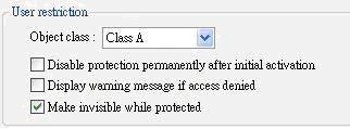
[SB_0] ~ [SB_2] are Set Bit objects which are set with different classes but selected “Make invisible while protected“. i.e. [SB_0] is class A, [SB_1] is class B, [SB_2] is class C. The setting of [SB_0] object:
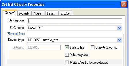
[SB_3] is Set Bit object with address [LB-9050] for user logout:
Step 3
After completing the settings of the objects, execute off-line simulation for the project.
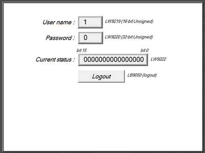
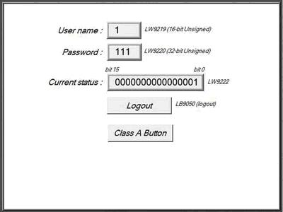
The illustration as below is initial screen of off-line simulation. At this time, no user is entered.
[LW-9222] shown “0000000000000000” means current user only can use object with “None” class. Moreover, [SB_0] ~ [SB_2] are the objects with the security levels of class A ~ class C and at the same time “Make invisible while protected“ is selected, therefore, [SB_0] ~ [SB_2] objects are hidden by the system.
Step 4
When the user inputs the password “111”, the screen will become:
Step 5
Next, when the user inputs the user 3’s password (333), the screen will become:
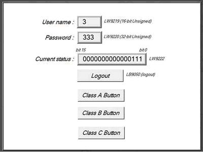
The user 3 is permitted to use object with class A,B,C. Now, bit 0 ~ bit 3 in [LW-9222] become 1 to confirm the current user is allowed to use objects with class A,B,C.
Step 6
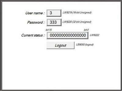
At this time, if [LB9050] is pressed and force current user to logout, the system will return to initial state. In other words, current user only can use object with “None” class.
MT8000/6000 series support SP-M, D, E, F and SPRT series printer. Please refer to instructions below to connect printer to HMI correctly.
1. SP-M, D, E, F
EPSON ESC protocol 9-pin printer.
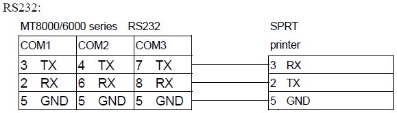
RS232 port
SIUPO – http://www.siupo.com
SP-M, D, E, F series
SP-E1610SK (paper width: 45mm)
SP-E400-4S(paper width: 57.5mm)

SP-MDEF
Recommended SP printer type for customers outside China
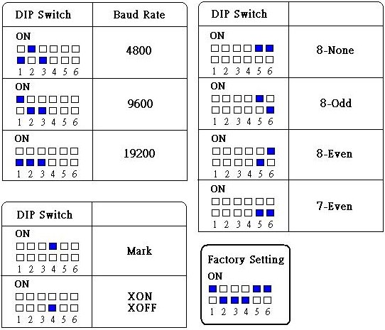
2. SPRT (SP-DIII, DIV, D5, D6, A, DN, T)
Step 1.
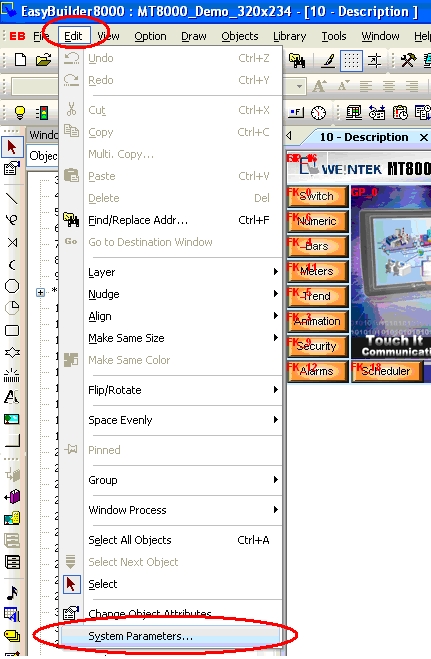
Click Edit menu /System parameter settings / Model tab to select SPRT printer.
Step 2.
The baud rate in serial interface mode is with options of 4800, 9600, and 19200bps. It is set by DIP switch on the control panel. Users can do some adjustments that meet their demands. Users can also select suitable baud rate according to figures below.
Step 3.
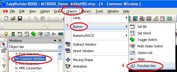
Create a Function key object or PLC control object / screen hardcopy to trigger printer.
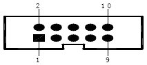
Wiring diagram:
The serial interface of SPRT printers are compatible with RS-232C standard, the interface socket is rectangle 10-pin female socket, which matches rectangle 10-pin male socket. The pin order of serial port is as below:\
After converting EB500 project to EasyBuilder Pro, the tag will be lost. The step below enable users to replace PLC address with tag name when importing EB500 tag library to EasyBuilder Pro.
Step 1.
Open Tag Library in EB500 project and select “Export” to save the tag as tgl file.
Note: Please do not use “Export CSV”, this one is not able to auto. replace PLC tag name in EB8000.
Step 2.
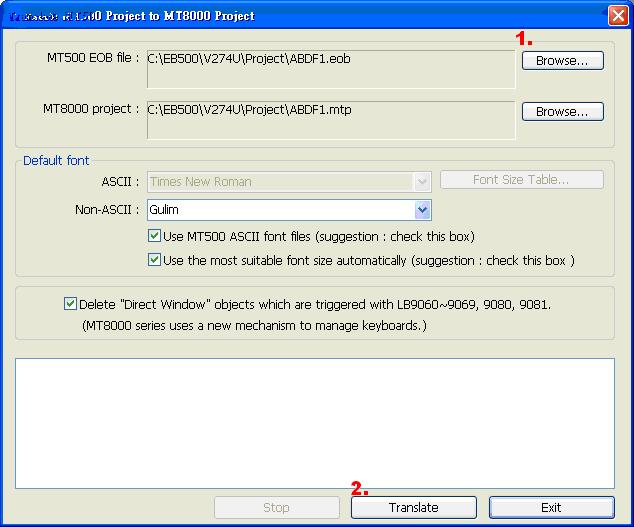
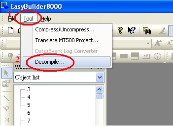
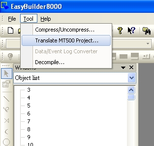
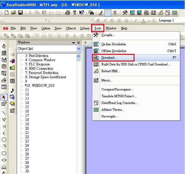
Open EasyBuilder Pro. Go to [Tool] and select [Translate MT500 Project…]
Step 3.
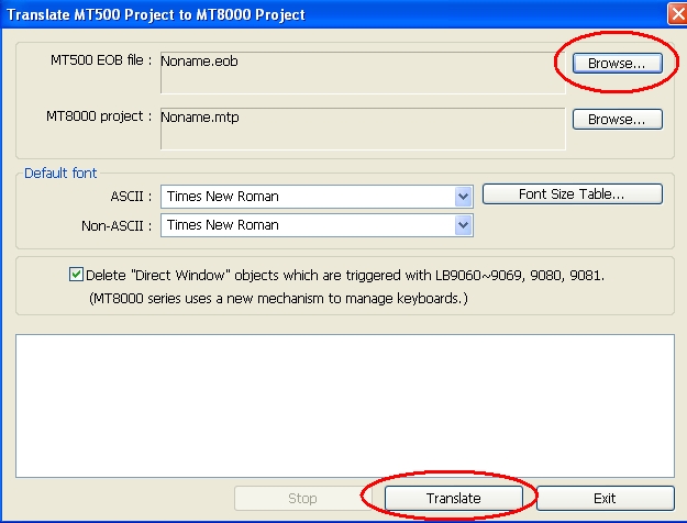
Select MT500 EOB file and click “Translate”.
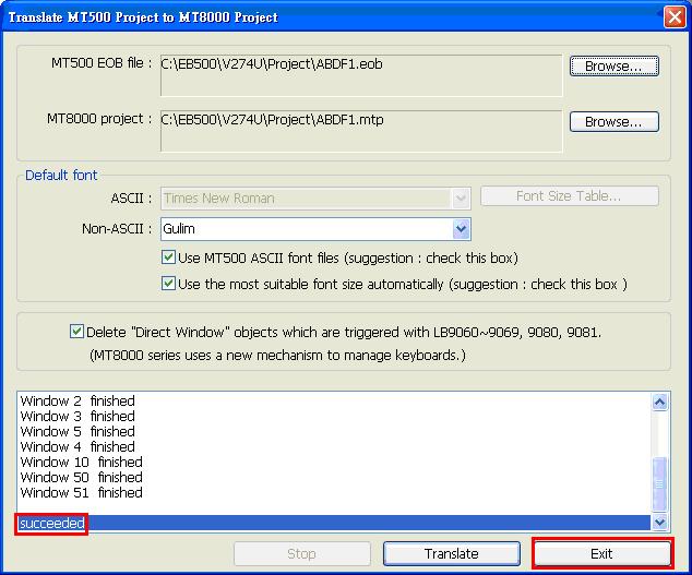
Step 4.
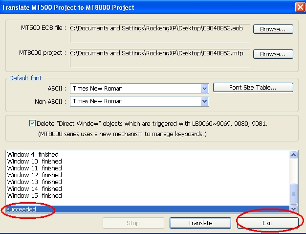
Select “Exit” after converting project succeeded.
Step 5.
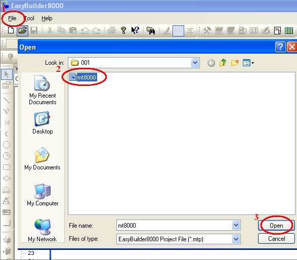
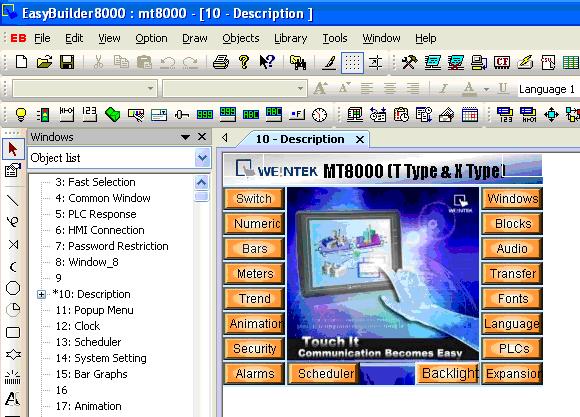
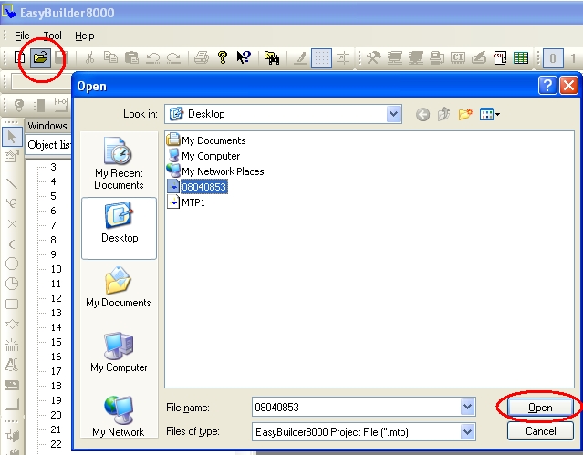
Open converted project in EasyBuilder Pro.
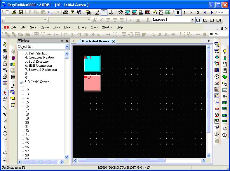
Step 6.
Open Address Tag Library and select “Load Tag File”.
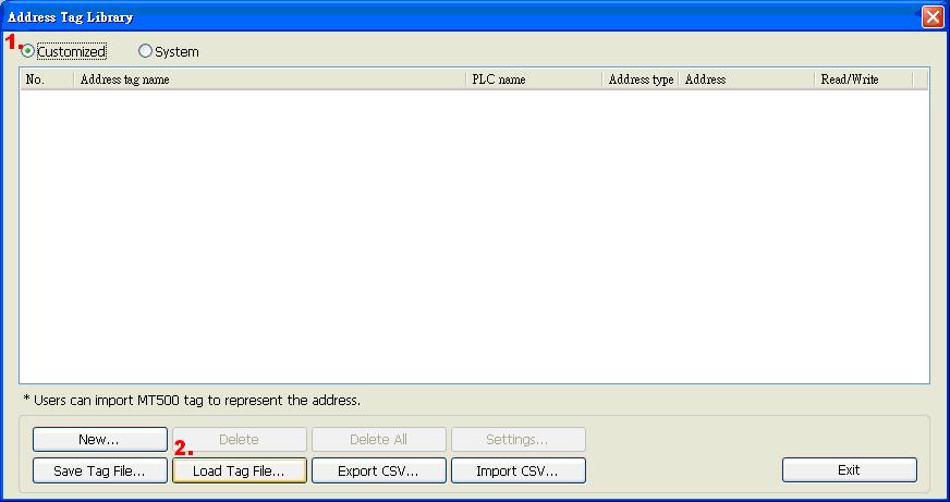
Step 7.
Choose the EB500 tgl file
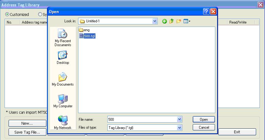
Step 8.
When a message “Use tag to represent the address” appears, click Yes.
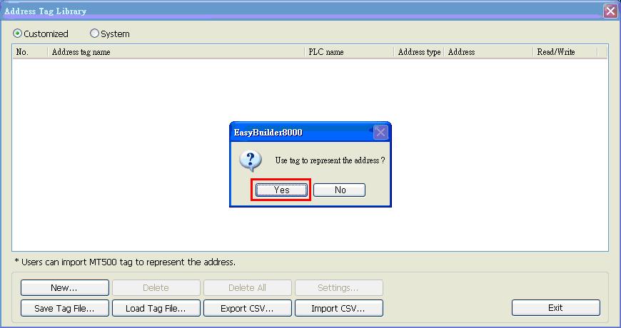
Step 9.
The object will be automatically replaced as PLC address by tag name.
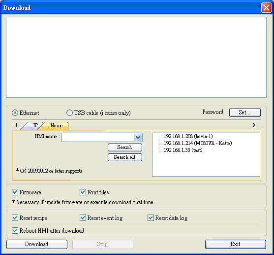
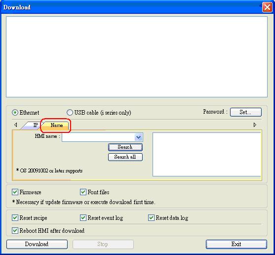
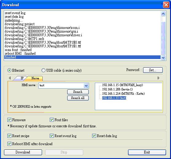
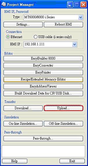
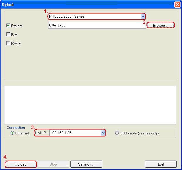
If users would like to download project through Ethernet, there are two ways for selection. One is to input HMI IP address for download; another is to input HMI name. Before downloading project through Ethernet, the IP address of target (HMI) must be set correctly in system settings in HMI. If “Auto Get IP Address” is selected, IP address will be automatically assigned from local DHCP network. While if “IP address get from below” is selected, IP address and other network information have to be inputted.
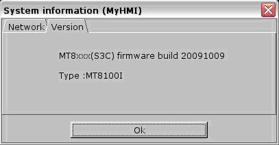
Hardware version: OS image 20091009 or later supports
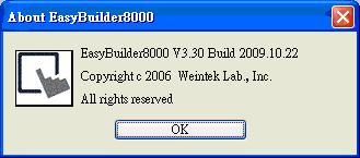
Software version: EB8000 V3.30 or later supports

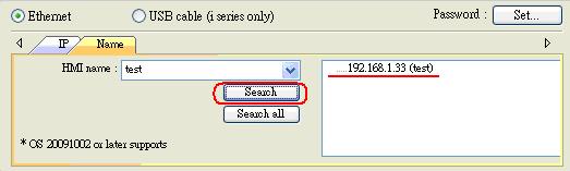 Or click “Search all” to search all HMIs in network.
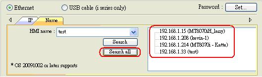
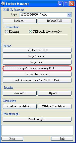
MT6000/8000 i series support the function of using USB to Mini USB cable to download / upload projects from PC. When using the USB cable to download project, PC is viewed as Master and HMI as Client. It is necessary to install EB8000V2.00 or newer version (EasyBuilder Pro) and USB driver of HMI on PC the first time using this function.
(The HMI models:MT6050i/MT6056i/MT6070iH/MT6100i/MT8050i/MT8070iH/MT8100i).
Note: USB driver is compatible with Windows XP service pack 3 and Vista.
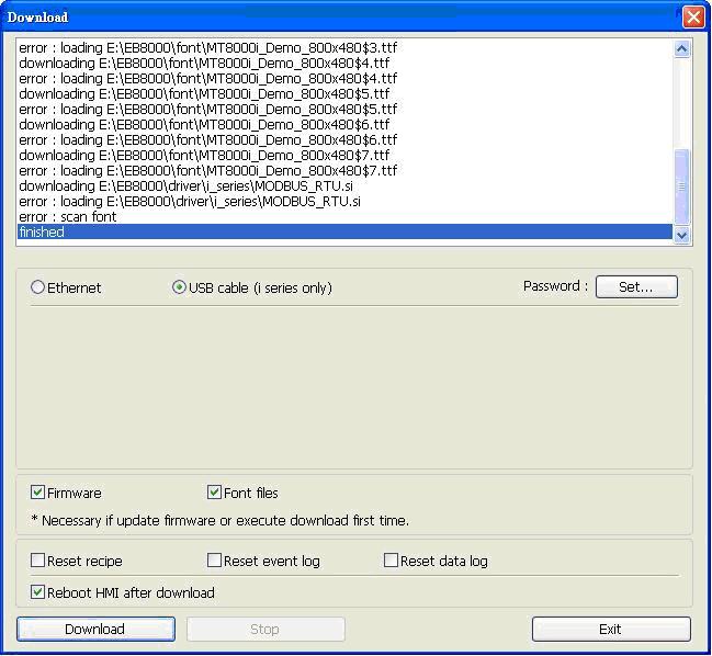
Troubleshooting:
If error messages appear as picture below when downloading project via USB cable, please check follow points:
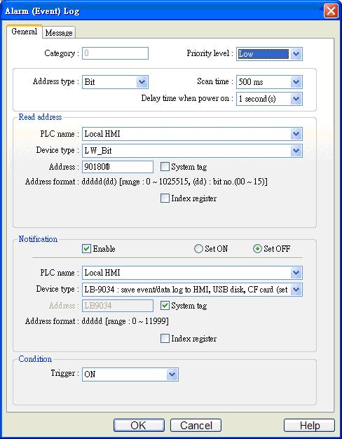
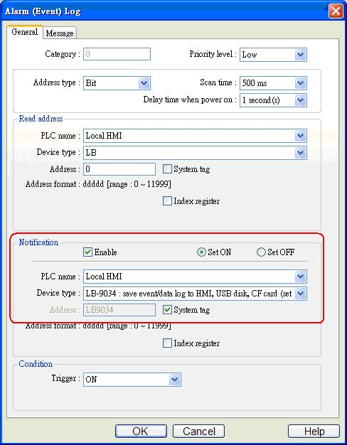 Hint: Users can set LW_bit 901800 to trigger LB-9034 every two minutes as pictures below.
If user does not login Windows XP as administrator, when compiling the project, an error message may appears as “Build font file failed, please do not use this font type…”.
Please follow steps below to correct the error. (Steps below are only available when PC hard-disk is not locked by administrator.)
Note:
Security tab for the properties of files or folders in Windows XP Professional is an important functionality that enables administrators and users to define security permissions and rights for particular user or group to access the computer resources. By default, Windows XP Professional follows recommended setting to enable the use of simple file sharing that hides the Security tab, leaving you with only General, Sharing, and Web Sharing & Customize tabs as in the Simple File Sharing UI.
For seeing the Security tab not hidden, just follow the steps:
Security tab is available only for Administrator or users with administrative rights. So make sure you login as one. And security can only be set in an NTFS partition. If you’re still having problem to reveal or display the Security tab on files or folder properties, check out the following registry hack and set the value to 0 or simply delete the key:
Hive: HKEY_CURRENT_USER
Key: Software\Microsoft\windows\CurrentVersion\Policies\Explorer
Name: Nosecuritytab
Type: REG_DWORD
Value: 1
If you’re using a Windows XP Professional system that is installed in a Workgroup, the Security tab is also hidden by default because in Windows XP Home Edition and Windows XP Professional, guests are forced to login a workgroup. Follow the instruction and information on Microsoft Knowledge Base where you need to set the value for ForceGuest registry key.
Screen capture is always required for users to edit manual guide. There are two ways of capturing the simulation screen display:
 The image is saved in the following path C:\EasyBuilder Pro\usb1\hardcopy:
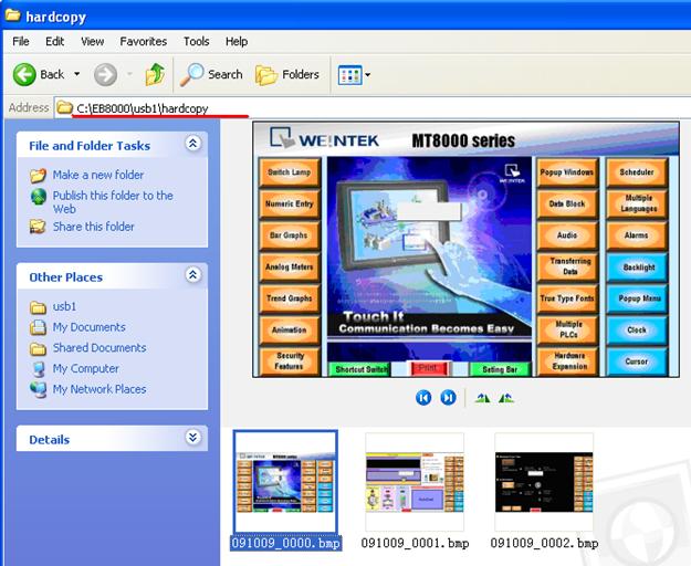
The following are the instructions for setting up the printer (take HP printer for example):
 There are two ways to start the printer:
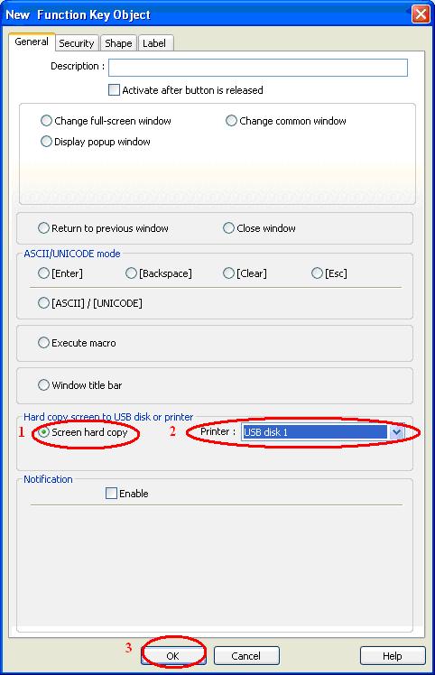
 3.2. In the “New Function Key Object” window, select “Screen hard copy” under the “General” tab. Select the printer: HP PCL Series (USB); Click “OK” to create a printer function key.
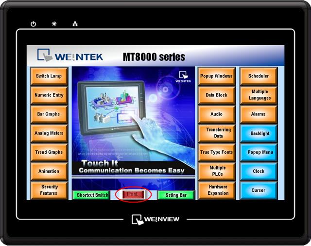
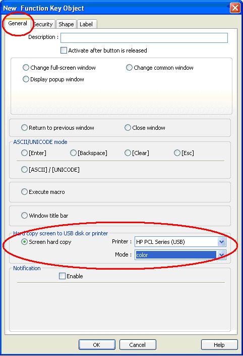 3.3. Connect the printer to HMI. You can now simply click the “Print” button object that you just created on the screen.
 4.2. Click “New” button in the “PLC Control Object” window;
 4.3. Select the corresponding PLC name; Set the “Type of control” to “Screen hardcopy”; Select the “Device type” and “Address” to M0; Select the “Trigger mode” to “OFF->ON”; Select the printer: HP PCL Series (USB), and click “OK” to complete. Run the program, setup the M0 address in the PLC program to start printing.Notice:
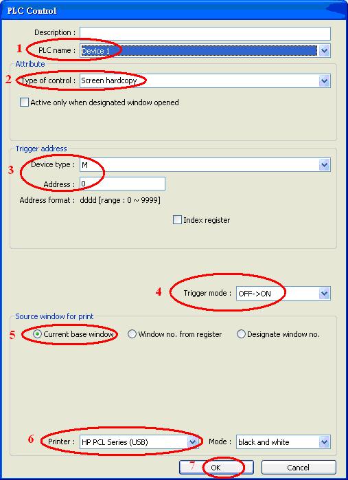
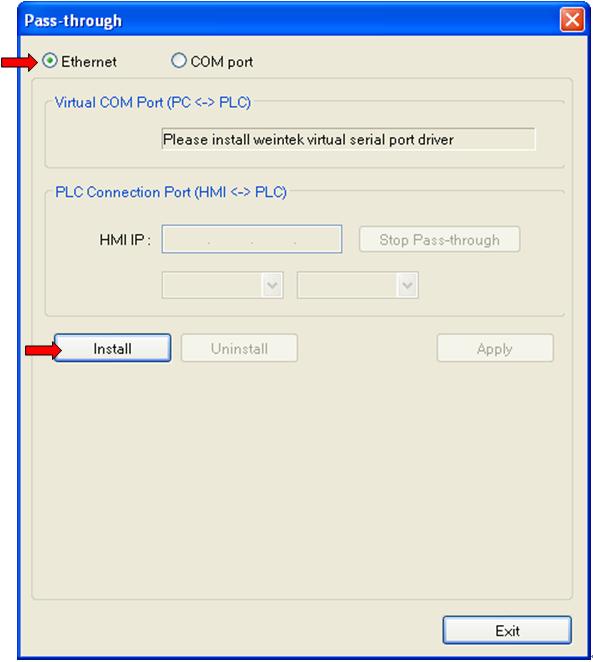
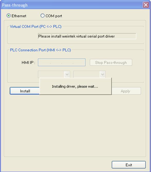
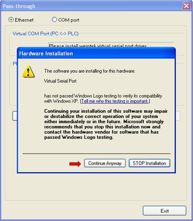
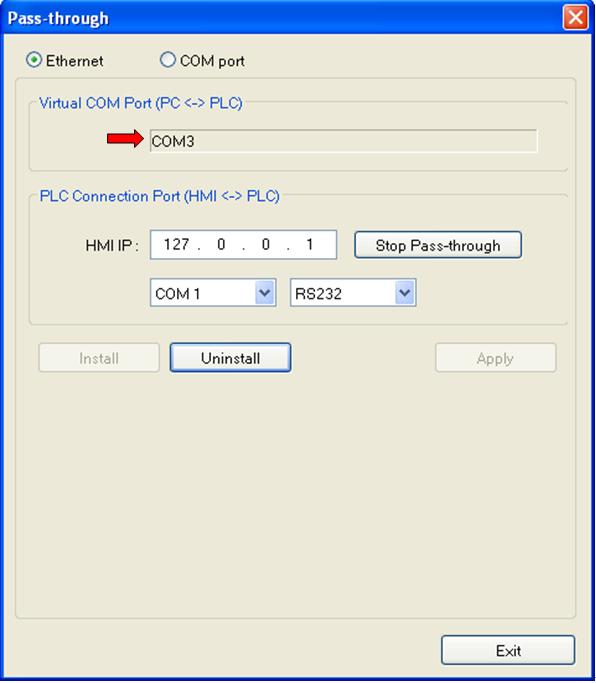
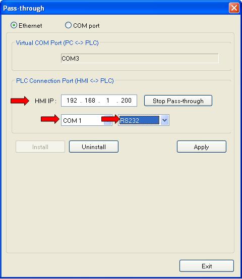
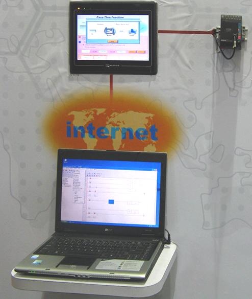
MT8000 provides Ethernet pass-through communication which allows PC to link to the PLC through the HMI. In this situation, the role of HMI is similar to a converter.
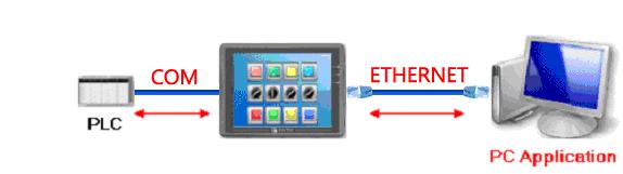
First, a virtual serial port must be created on PC. The application program on PC can communicate with PLC through this virtual serial port.
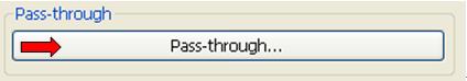
Instructions are as follows:
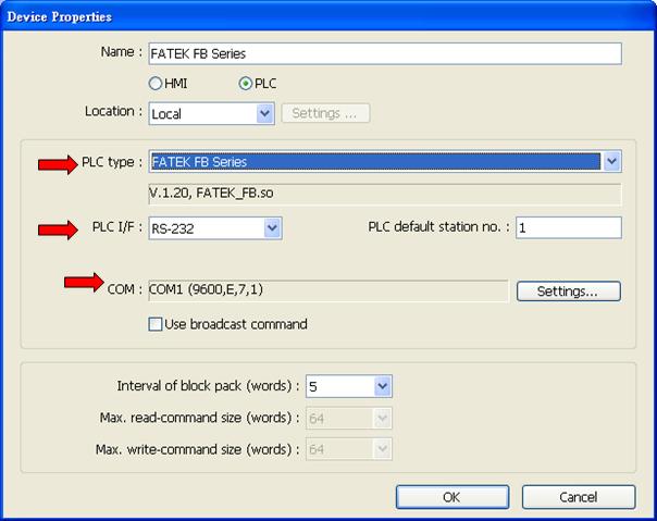
 Notice: Before translation, please check that if EasyBuilder Pro does support the corresponding PLC type. (Check out “Edit / System Parameters / Device / New / PLC type“)
When a large image is displayed, for example, using a 65536 color image as background image may cause the HMI process speed to slow down. Users can follow the instructions below to speed up the display rate of image.
Step 1
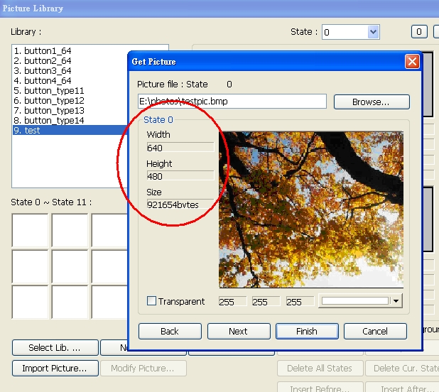
While using an image file as background in full screen, the image size shouldn’t exceed the display window size. A BMP format image file is recommended. The following picture shows that if the display window size is 640*480, the size of imported image will be limited to 640*480. (The image size will be shown in the “Get Picture” preview window).
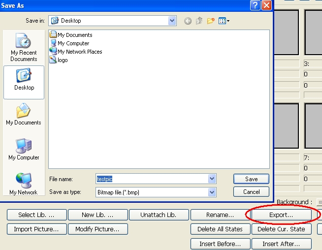
If the image size exceeds display window size, you can export the image and resize it by using WINDOWS image processing tool.
Step 2
The picture object needs to use original dimensions. Check the “Set to original dimensions” check box in the “New Picture Object” dialog box.
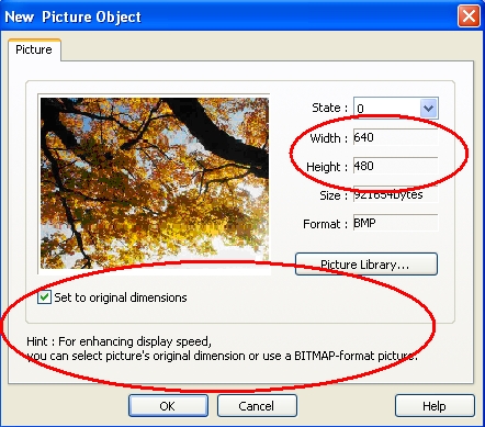
Sometimes, the image size already exceeds the display window size. Even though the “Set to original dimensions” option is checked, the image still cannot be displayed in original size. You should go back to step 1 and follow the instructions to resize the image and import it again.
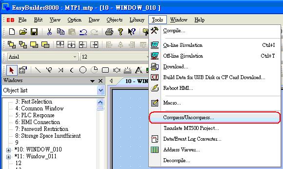
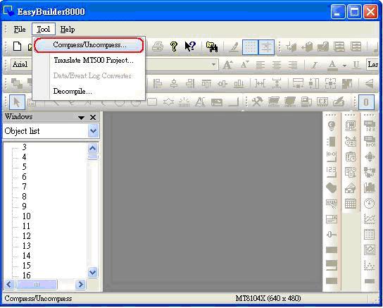
An EasyBuilder Pro project contains the source project file (*.mtp), and a number of library files (*.flb, *.blb, *.plb, *.slb, *.snd, *.lbl, and *.glb). These can be individually copied to another location for archiving, or to select theCompress/Uncompress option from EasyBuilder Pro’s Tools menu.
Step 1.
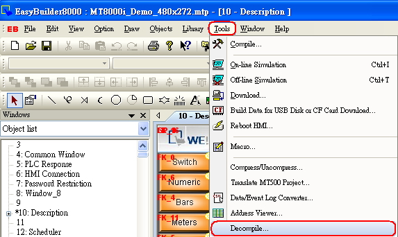
Click Compress/Uncompress from Tools menu.
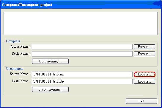
Step 2.
The following dialog is displayed. Click “Browse” to select source project for archiving.
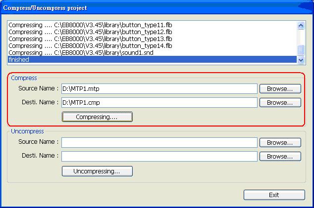
All of the files associated with the project are compressed into a file, with a name of the form *.cmp. The compressed CMP file can be properly archived when this step is successfully completed.
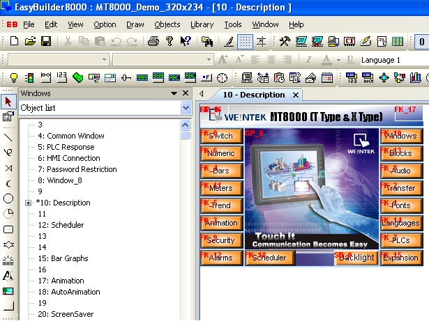
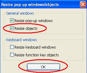
※(Take the switch between MT8056T (320*234) and MT8104X (640*480) for example)

For MT6070T and MT8070T have particular aspect ratio (resolution: 480*234), before to display square or circle, users have to calculate the width and height for object’s profile.
The formula for width and height is: WIDTH : HEIGHT = 1.15 : 1
For example: To make a 80×80 square.
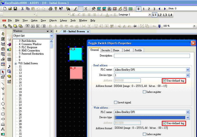
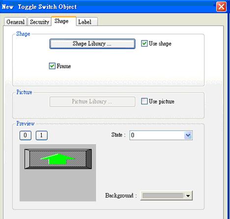
First of all, create a toggle switch object and select the picture and press OK.
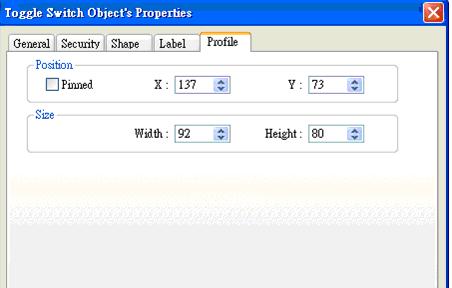
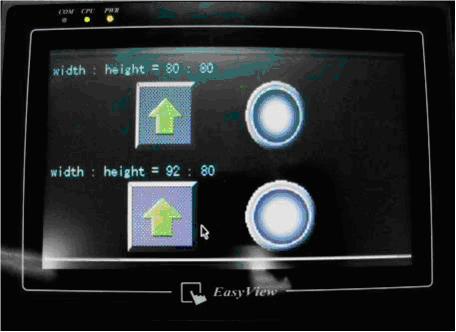
And then double click this object into Toggle Switch Object’s Properties / Profile.
The formula for width and height is: WIDTH : HEIGHT = 1.15 : 1, so fill in the width: 92 and height: 80. (Width: 80*1.15 = 92)
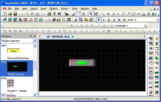
Press OK, the object looks like a rectangle at this moment.
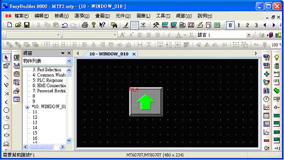
After downloading project to HMI, the object will become square.
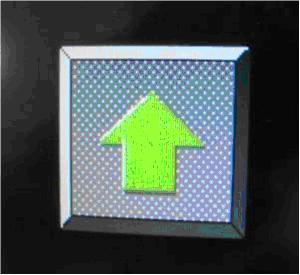
The formula of circle is the same as square setting as below picture.
On the upper side of screen, the width : height = 80:80, looks like a rectangle and ellipse.
On the lower side of screen, the width : height = 92:80, looks like a square and circle.
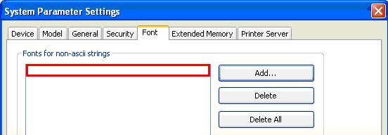 2.2. The selected Chinese font is invalid, as shown in picture 3;
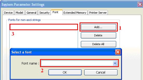 3.2. Select a valid Chinese font, as shown in picture 5;
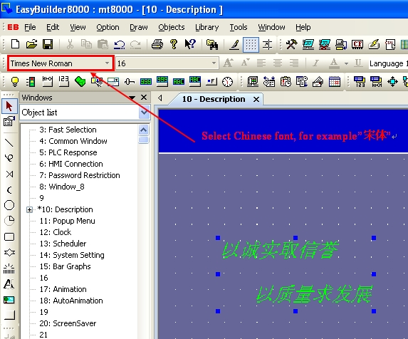
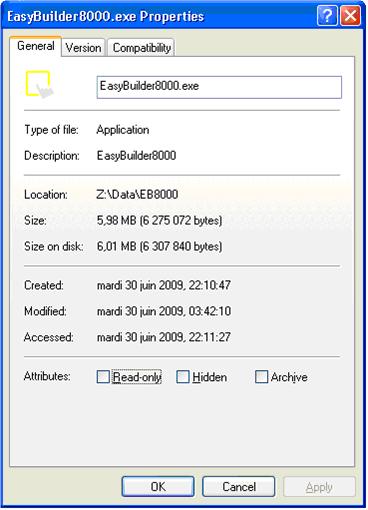
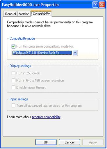
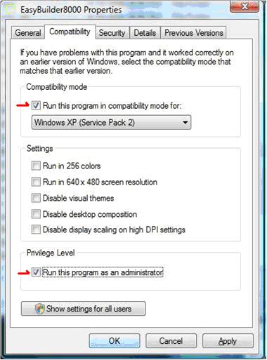
Example showing the EasyBuilder8000.exe file Properties.
When executing EasyBuilder Pro.exe, if an error message appears as below, Please check if AVAST ANTIVIRUS software is installed on your PC.
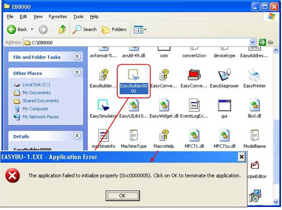
AVAST ANTIVIRUS software of program version 5.1.889 or later has a possibility to conflict with EasyBuilder Pro software and cause failure in EasyBuilder Pro execution. To deal with this, please pause AVAST ANTIVIRUS software or remove it from your PC.
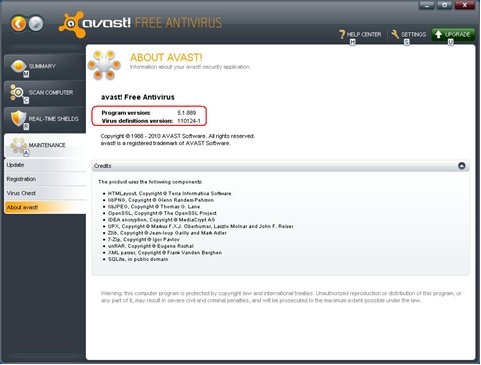
Please use EasyBuilder Pro V4.43 for using AVAST and EasyBuilder Pro simultaneously.
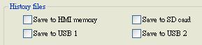
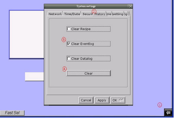
The HMI memory of MT8000/6000 series is able to store event log data. There are three ways to clear historic data files in HMI memory.
 or click Download button >> write in HMI IP >> tick [Reset event log] and [reboot HMI after download] >> Download
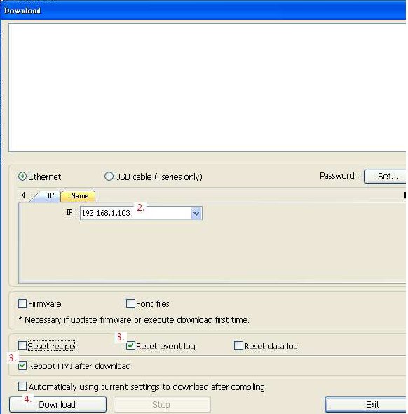
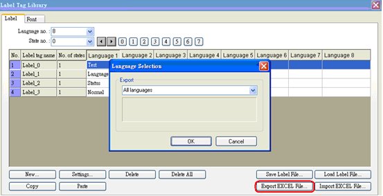
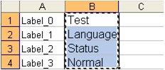
EasyBuilder Pro Label Library Language Translation Manual
(English to Italian and Simplified Chinese)
 A [Success!] message is shown upon completion of the export.
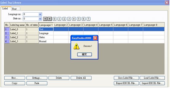 The selected labels are exported to EXCEL file.
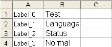
 To translate using Google, link to Google homepage first: http://www.google.com/.
 Paste the copied items to the translating field of Google, select from and to which language, click [Translate], and see the result on the right side.
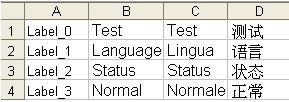
b. English->Simplified Chinese

This demonstration shows how to translate English to Italian and Simplified Chinese.
Copy the translated items and paste to the EXCEL file columns [Language 2] and [Language 3].
 Click [Import EXCEL File] and select the file to be imported.
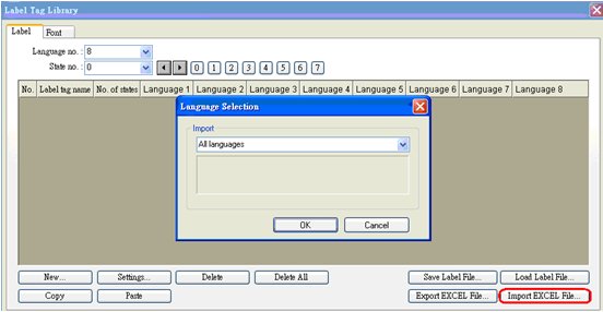 The EXCEL file is then successfully imported.
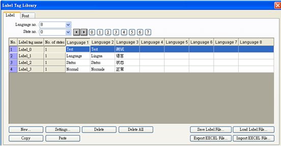
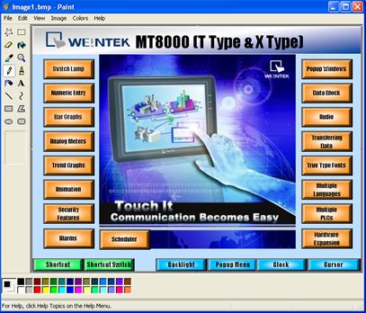
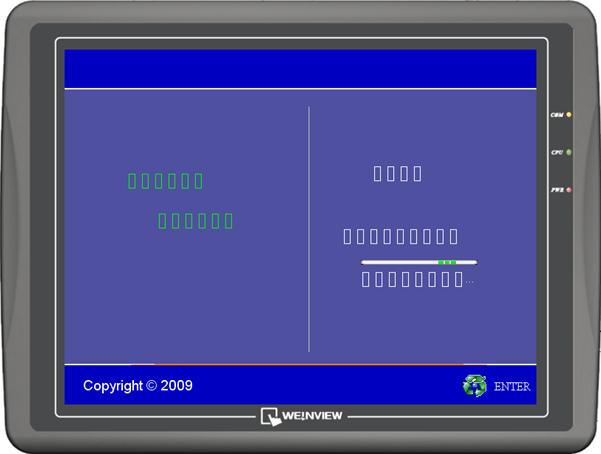
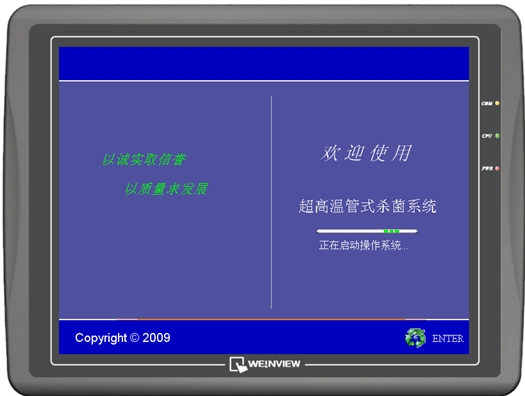
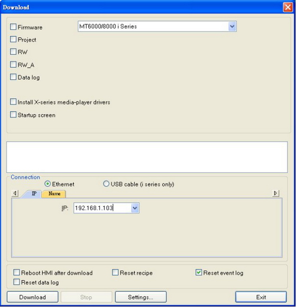
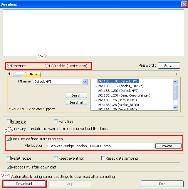
MT8000/6000 i series HMI supports users to define their own startup screen, such as enterprise trademark logo, etc. The format of the picture used is BMP and can not exceed the resolution.
The assigned BMP picture will be downloaded to HMI. After downloading, HMI will reboot, this picture will be shown after rebooting, and then load in the project. Users are allowed to use their logos as the start up screen through this method.
Note: Only support i series and OS Image 20090415 or later)

There are 2 ways to download start up screen as shown below:
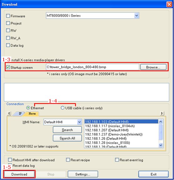
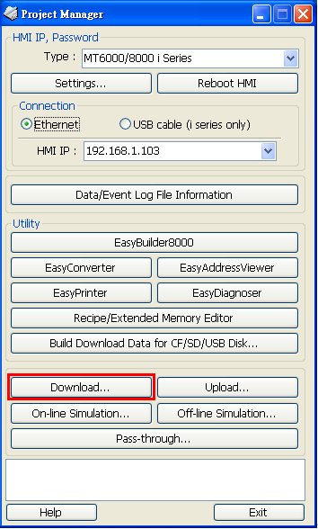 1-3 Select a BMP picture that suits the size of HMI screen,
1-4 Set the IP address or use a USB cable.
1-5 Click [Download]; reboot HMI to see the successfully set picture display when HMI starts up.
 2-2 Select a BMP picture that suits the size of HMI screen,
2-4 Click [Download]; reboot HMI to see the successfully set picture display when HMI starts up.
CSV is a kind of text file that uses comma sign to separate values. However, in the operating systems of some countries, semicolon is used as list separator, therefore when exporting CSV file using RSLogix500 software, semicolon is used and may cause EasyBuilder Pro to fail at identifying the file content.
Change the list separator to comma sign through the following steps then export CSV file for EasyBuilder Pro to read.
Note: The countries that run operating systems using semicolon as list separator are listed below, please complete the setting before exporting CSV file.
Czech | Netherlands | France | Germany | Greek | Italy | Spain | Poland | Sweden | Finland | Russia | Malaysia | Turkey
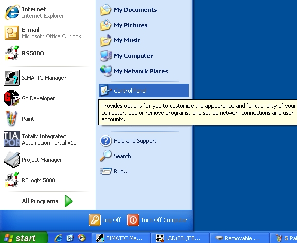
Select [Control Panel].
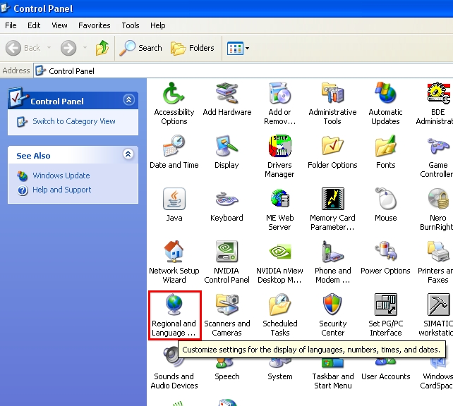
Select [Regional and Language].
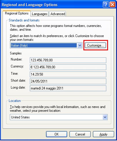
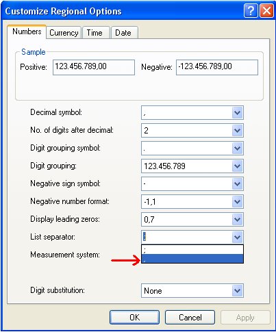
In REgional Options, select [Customize].
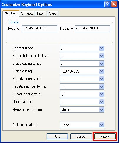
Select comma sign in List Separator.
Click [Apply] and [OK].
After finishing settings above, use RSLogix 500 to export CSV file, the CSV file will use “,” as default separator.
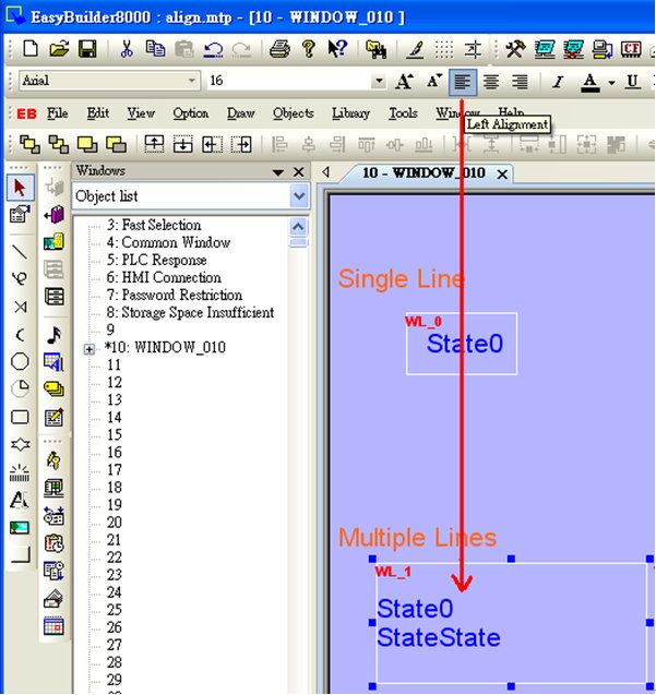
In EasyBuilder Pro, there are two different ways to align the text on the object, one is to click the icons on the toolbar and the other is to set on object setting dialog.
By clicking the icons on toolbar (Left Alignment | Center Alignment | Right Alignment), the text, no matter single-lined or multi-lined, will be seen as one single label and will align to the outline of the object.
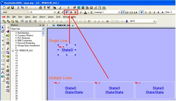
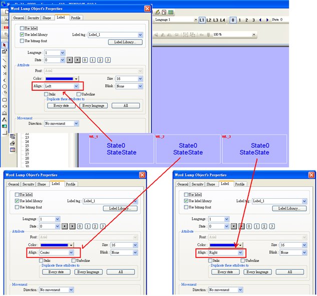
By setting Label>>Align on object setting dialog, the multiple lines of the text will align in the way set. This is a line by line alignment.
The line by line alignment of the multi-lined text can be done using Label>>Attribute selection on object setting dialog.
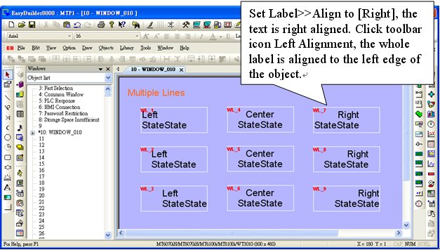
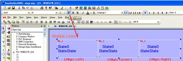
If an object is set to [Left] for [Align], when clicking [Left Alignment] on toolbar, the multi-lined text will be aligned along the left edge of the object.
The way above is same for [Align Center] and [Align Right]. The multi-lined text will display according to the setting of Label>>Attribute>>Align.
The illustration below shows when [Left Alignment] icon is clicked, the text content are still displayed in the way they are set in object setting.
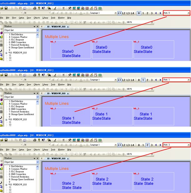
If object text is set with multiple states, tick [Tracking], in this way when moving text in one state, the texts of other states will also be moved in the same way.
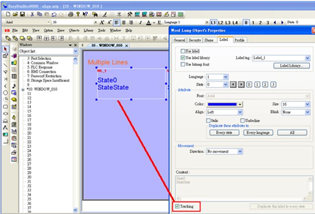
Move object text in state 0; check the other states to see if the texts in those states all move the same way as in state 0. If [Tracking] is not selected, only text in one state will be moved.